september 30 2021
Converting 24 bpp bmp to 16 bpp st7735 display picture
Been writing a project of displaying .bmp images from sd card on a tft lcd display.
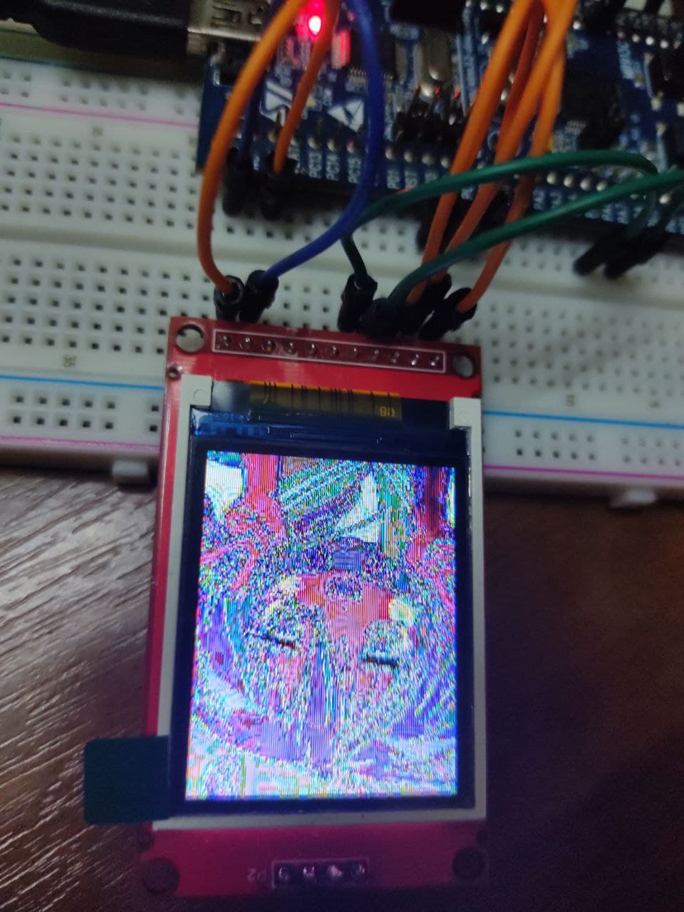
At some point, i finally managed to display the pictures, but something was really off.
The colors were inverted.
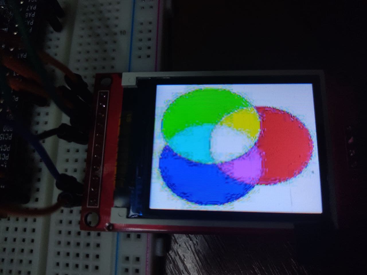
The funniest thing was: when i tried to display a picture with solely RGB colors, it really worked correctly.
Except having some weird artifacts, which you can see on the image below.
I talked to someone at that moment, who noticed these artifacts, which i didn't..
And, after reading my excerpt from the conversion algorithm, said something about the weirdness of using "lower" bits.
This gave me an idea! The one, which explains why pure RGB colors work, but not the hues.
The thing is: For example, pure green 24 bpp pixel would be 00000000 11111111 00000000, while the hues would be something like a mess of 10110110.
Thus, such bit masks as 0b11111000 and 0b00011111 won't make any difference for pure colors, but will have a significant impact on hues!
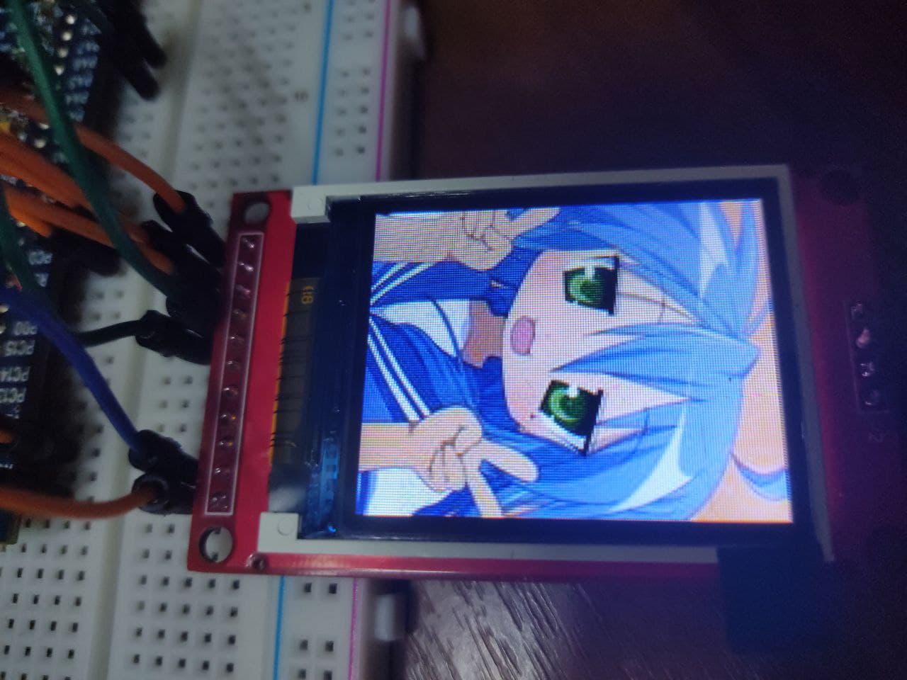
I instantly changed the mask to the first abovementioned one, and you might guess it worked! xD
september 21 2021
About hardware "debug" and "useful" documentation
Spent some time debugging my SPI SD card adaptor - it simply wouldn't start.
I retried everything, including fully resturing project's fork and replacing SPI peripheral with the first one.
At some point, i wasn't sure at all what to do, so i decided to take some arbitrary actions.
Suddenly, i tried to supply the module with 5V instead of 3.3V. It immediately worked out!
Lmao. The funny part is - the documentation says it's 3.3V compatible. I laughed out then for quite a while.
Be careful with chinese module clones.
september 15 2021
I'm trying to set up timer input capture for quite a few days already (stm32 + cmsis + spl).
Seems really impossible. No matter what I do, capture/compare registers (CCR1, CCR2) always return 0.
The timer itself works, because CNT (count) register returns valid values between 0...max (max = 9999 in my case).
I tried to use both TIM1 and TIM2 for the input capture, but neither worked.
I'm posting this here as a reference note for myself in the future - I guess, you will laugh once reading this. xD.
What a noob i am. Gonna keep trying to set it up, though, i guess, at some point (around several days) I'm gonna give up and return to this thing later.
Btw, I need this setup for using an ultrasonic sensor - a device for measuring distance to the closest obstacle.
It has two pins - Trigger and Echo.
Its protocol is very simple - you send a 10 μs trigger and it returns a signal, the length of which is proportional to the measured distance.
(It measures the distance by sending 8 40 KHz ultrasonic signals, of course.)
So, to know the measured distance, i need to measure the Echo pulse width... What a pity, I can't do this yet. It just isn't working out.